1. Identify the chart and the installed crane
Begin with the crane identification and the chart revision. Match the boom arrangement, extensions, attachments and installation information to the actual equipment. A truck's drive layout describes the carrier, not the lifting capacity of its crane. Likewise, an off-road chassis description does not establish that the ground beside the truck can support a lift.
Compare the equipment identifiers on the vehicle, chart and operating manual. Where a document covers several variants, find the instructions that apply to the installed one. Do not transfer a chart from a similar model name or treat a sales illustration as the operating document. If the required identification or chart is missing, obtain it before deciding that the proposed work is within capacity.
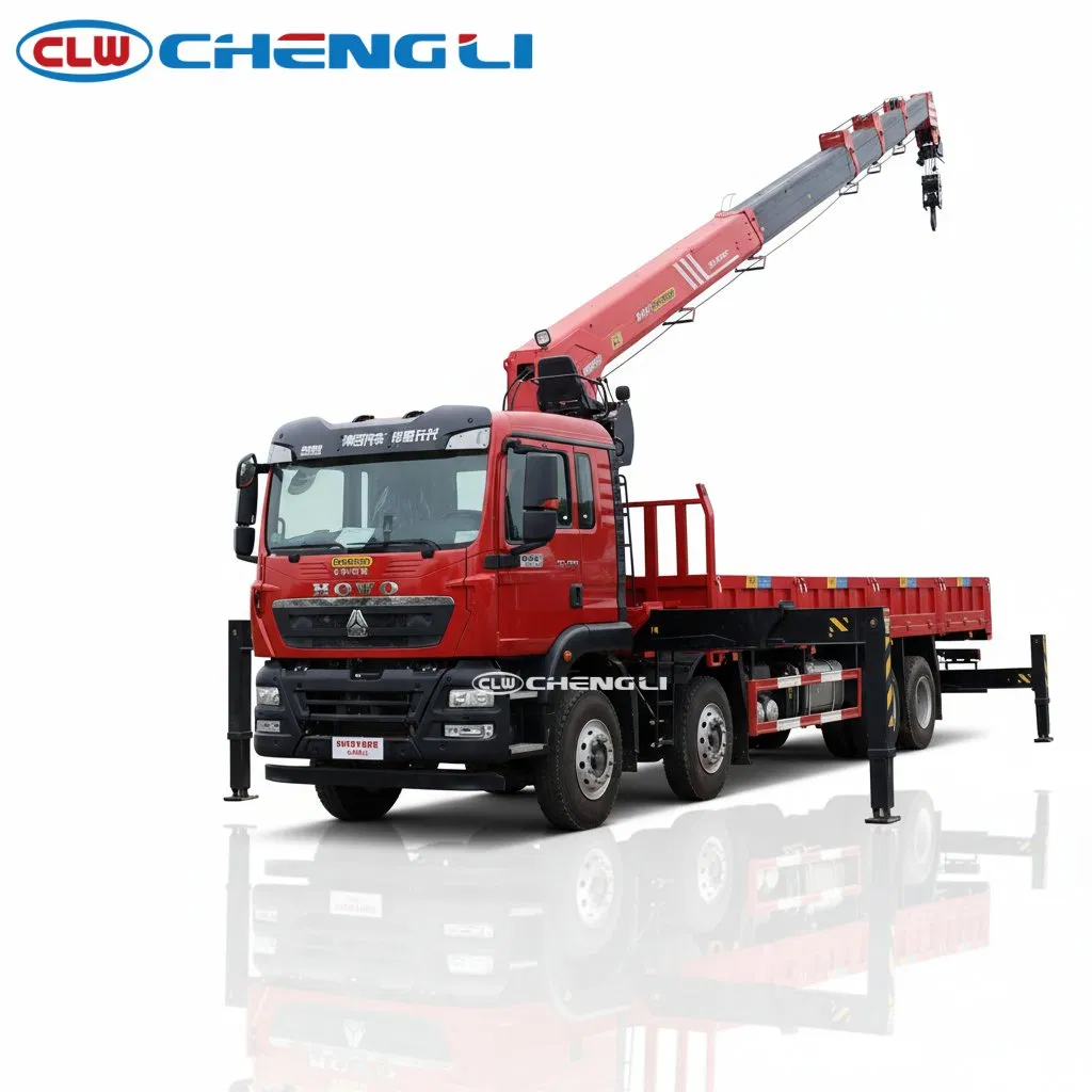
These vehicles from the truck-mounted crane range illustrate different equipment descriptions to reconcile. The table is an identification comparison, not a lifting-capacity chart, and no permissible load is inferred from it.
| Vehicle | Equipment information to match | Information required for a lift assessment |
|---|---|---|
| HOWO 8×4 crane truck with SQS350-5 | SQS350-5 crane; five-section straight boom | Chart for the installed boom, support arrangement and working sector |
| JMC double-cab crane truck | Compact telescopic boom; double-cab truck | Exact crane identity, extensions, attachments and the matching chart |
| CL52306TQZ6ZQ off-road crane truck | 6×6 carrier; four-section straight boom | Installation documents, support conditions and the applicable operating chart |
2. Find radius and boom configuration without guessing
Read the chart's definition of working radius first. It normally concerns the horizontal distance from the crane's stated rotation reference to the load line, rather than the distance measured from a tyre or the nearest side of the truck. Identify the correct reference point in the specific manual. The hook's height, the boom's length and the horizontal radius are different measurements and cannot be substituted for one another.
Next identify the boom configuration that will be used throughout the intended movement. A chart may separate extension arrangements, attachments or operating modes. Use the symbols, units and notes printed on that chart. Check whether the load must pass through a less favourable position between pickup and placement; being within capacity at the starting position does not establish that the whole movement is suitable.
Longer outreach commonly reduces the load available for a particular configuration, but this does not create a universal calculation rule. Do not extend a line, interpolate between entries or use a proportional calculation unless the applicable instructions explicitly permit that method. A reach diagram may show geometry without providing a lifting allowance for every point drawn on it.
3. Apply support conditions, deductions and restrictions
Read the support conditions alongside the load entries. The specified stabiliser deployment, working sector and installation conditions form part of the rating. A value for one setup is not automatically valid for a partly deployed support arrangement or a different working direction. Follow the particular crane's instructions rather than assuming that every truck uses the same support procedure.
Ground support needs its own assessment. The fact that a truck can drive onto a surface does not establish that the surface can carry concentrated stabiliser forces. Underground features, edges and changing surface conditions can matter. The responsible lift planner and operator need the support information required by the installation and site conditions; a product photograph of deployed stabilisers cannot provide that assessment.
Check how the chart accounts for the hook, lifting accessories, attachments and any equipment included in the suspended load. Use the stated deduction rules and units. Do not assume that a chart entry is automatically the net weight of the item being delivered. If the inclusion or deduction is unclear, resolve it with the appropriate technical documentation before approving the proposed lift.
Observe all other operating restrictions in the manual. The chart does not cancel limits associated with the equipment, environment or operating method. A warning or control system is not a reason to exceed the applicable instructions, and a purchasing comparison is not a substitute for operator competence or a lift plan.
4. Keep lifting assessment separate from road loading
Road payload and crane lifting capacity answer different questions. Payload concerns the load carried by the completed vehicle within its applicable mass and axle constraints. Crane capacity concerns a suspended load under particular operating conditions. The crane, body and fitted equipment also contribute to the completed truck's mass; a large lifting label does not establish how much cargo may be transported on the deck.
For procurement, request the installed-crane documents and a separate completed-vehicle mass and loading schedule. Describe the intended loads, pickup and placement positions, access and support constraints. Ask the supplier to identify the exact configuration proposed for those duties, rather than choosing by the largest number in a model description. The crane selection guide covers boom and carrier choices; this article concentrates on reading the operating information.
For a planned job, the responsible team should reconcile the load, rigging, travel path, radius, configuration, supports and restrictions with the actual chart and manual. If they do not match, stop the assessment and resolve the missing information. Buyers serving Nigeria, Ghana, Kenya, Tanzania, Zambia or Zimbabwe should keep this technical assessment separate from any current destination-specific operating requirements.